Wind tunnel simulation of a sports car- ANSYS FLUENT
For this project a 3D wind tunnel analysis was conducted. To achieve this, a rectangular domain was first created in CREO.
Then a fine mesh was created on the surface by using ANSYS. A fine mesh with skewness of 0.24066 was obtained (considered good quality mesh). Initial boundary of 44.7m/s (100 miles/h) velocity at the inlet and 0 Pa gauge pressure was given. Maximum velocity of 6.13e1 m/s and maximum pressure of 1.227e3 Pa was obtained from ANSYS FLUENT which can be see in the following images/plots.

Pressure contour
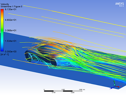
Velocity streamline

Mesh plot
Impact analysis of a bullet projectile- ANSYS WORKBENCH
In this project an explicit dynamic analysis was performed on a bullet which hits an assembly of 4 plates with an initial velocity of 800 m/s. Event time was set to 0.00015 seconds. A fine mesh was generated around the point of impact for more accurate results. Maximum equivalent stress of 1.2e9 Pa, Equivalent plastic strain of 2.4677 m/m and a total deformation of 0.11778m was obtained which can be seen in the following images.
Von mises stress plot

Mesh plot
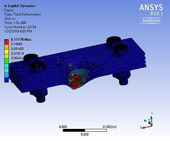
Deformation plot
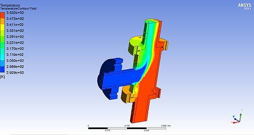
Fluid structure interaction (FSI) in a T-Junction
In this project hot and cold fluids were entering in the T-junction. Because of the temperature difference different thermal stresses were being produced during the mixing. So first of all fluid flow was analysed in ANSYS CFX. Output of CFX was then taken to do the static thermal analysis of the junction for temperature distribution. That temperature distribution was then given as input to Mechanical solver to calculate static stresses and ultimately from that to thermal stresses. Results are shown below.

Project schematic
Temperature plot in fluid flow (CFX)
Steady state thermal temperature plot
Thermal stresses plot
Conjugate heat transfer and thermal stress of 4 intake exhaust manifold (ANSYS AIM)
In this project 4 intake exhaust manifold of an automobile was analysed for which flow analysis was performed first to calculate the fluid flow and get temperature distribution. These results were later used as an input for thermal stress analysis and following results were obtained.
Fluid flow through the manifold

Structural mesh
Pressure contour
Displacement contour

Fluid mesh
